The contact person at Shenzhen Abluetech Technology Co. LTD is:
May Cat
Shenzhen Abluetech Technology Co. LTD
Web: www.abluetech.com
Email: maycat@abluetech.com
PH/WA: +8618682464199
The following circuit shows a example implementation for the Abluetech PTR9813 Module. Each pin and its functionality is described in the table below.
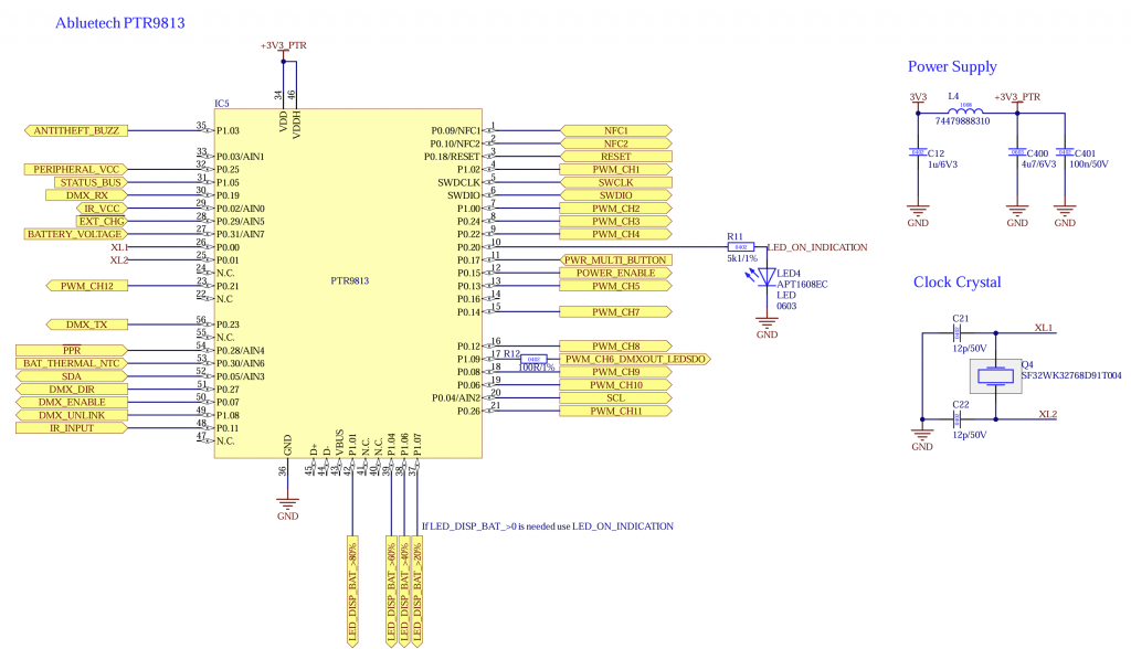
| Pin | Description | Mandatory | Function | Use | Wiring | |
| P0.04 | SCL | No | I2C Clock for for peripherals like motion, battery charge controller, battery gauge and display | Pull Up (4k7) | ||
| P0.05 | SDA | No | I2C Data for for peripherals like motion, battery charge controller, battery gauge and display | Pull Up (4k7) | ||
| P0.11 | IR_INPUT | No | IR Sensor Input for IR Remote. Output from IR Sensor. For Example: IRM-H6XXT/TR2 Vishay TSOP2436 | |||
| P0.15 | POWER_ENABLE | No | Output Turns on and off power from components needed during normal operation like LED Driver, additional controller, Motor driver, etc..Needed to make sure the current consumption while sleeping is minimal. If Battery Charge Controller is used the controller can be set to sleep instead this pin. | Pull Down (100k) | ||
| P0.17 | POWER_BUTTON_SWITCH | No | Input Button: Turn fixture on/off and unlink Switch: Turn fixture on/off | – | – | |
| P0.18 | RESET | Yes | Programming Reset | – | – | |
| P0.20 | STATUS_LED | No | Output: Signal Status LED | – | – | |
| P1.05 | STATUS BUS | No | UART RX for receiving additional information like battery state, etc.. You can find additional information under STATUS Interface | – | – | |
| P1.09 | PWM_CH6_DMXOUT_LEDSDO | No | Output Multiple Functions: PWM Channel 6 DMX Out (TX) LED SDO (WS2812) | – | – | |
| P0.02 | IR_VCC | No | Output: Switchable supply voltage for IR Sensor (Needed for IR Remote) | – | – | |
| P0.09 | NFC1 | No | NFC Antenna | – | – | |
| P0.10 | NFC2 | No | NFC Antenna | – | – | |
| P0.29 | /E/X/T/_/C/H/G | No | Battery Management: Charging indication Input Is only used if no battery charge controller is used and battery functions are available | Low: Charging High: No charging | – | |
| P0.28 | /P/P/R | No | Input: Battery Management: Power Presence Is mandatory if battery functions are necessary | Low: Power available High: No power –> battery powered | – | |
| P0.30 | BAT_THERMAL_NTC | No | Input: Battery Management: Battery NTC | Connect NTC using resistor divider. The resistance combination can be selected in firmware | – | |
| SWDIO | SWDIO | Yes | SWD Programming Data | – | – | |
| SWCLK | SWCLK | Yes | SWD Programming Clock | – | – | |
| P1.02 | PWM_CH1 | No | PWM Output Channel 1 | – | – | |
| P1.00 | PWM_CH2 | No | PWM Output Channel 2 | – | – | |
| P0.24 | PWM_CH3 | No | PWM Output Channel 3 | – | – | |
| P0.22 | PWM_CH4 | No | PWM Output Channel 4 | – | – | |
| P0.13 | PWM_CH5 | No | PWM Output Channel 5 | – | – | |
| P0.14 | PWM_CH7 | No | PWM Output Channel 7 | – | – | |
| P0.12 | PWM_CH8 | No | PWM Output Channel 8 | – | – | |
| P0.08 | PWM_CH9 | No | PWM Output Channel 9 | – | – | |
| P0.06 | PWM_CH10 | No | PWM Output Channel 10 | – | – | |
| P0.26 | PWM_CH11 | No | PWM Output Channel 11 | – | – | |
| P0.21 | PWM_CH12 | No | Optional PWM Output Channel 12 | – | – | |
| P0.25 | PERIPHERAL_VCC | Yes | Output: Use this as a switch for 3V3 supply for example for the NTC | |||
| P0.31 | BATTERY_VOLTAGE | No | Input: If battery functions are needed but no battery gauge is used this can be used instead as a rough battery state measurement | |||
| P0.19 | DMX_RX | No | DMX for DMX /RDM Support | |||
| P0.23 | DMX_TX | No | DMX TX for DMX /RDM Support | |||
| P0.27 | DMX_DIR | No | Output: Direction RS485 for DMX /RDM Support | |||
| P0.07 | DMX_ENABLE | No | DMX Enable/ Disable (Save power) | |||
| P1.08 | DMX_UNLINK | No | DMX Unlink for WDMX/ CRMX which is connected via Uart | |||
| P1.01 | LED_DISPLAY_BAT_>80% | No | Display battery LED > 80% | |||
| P1.04 | LED_DISPLAY_BAT_>60% | No | Display battery LED > 60% | |||
| P1.06 | LED_DISPLAY_BAT_>40% | No | Display battery LED > 40% | |||
| P1.07 | LED_DISPLAY_BAT_>20% | No | Display battery LED > 20% |
The following components should be used:
- Abluetech PTR9813 or PTR9813+
- Crystal „EPSON FC-135 32.7680KA-AC0“ or „SF32WK32768D91T004“