Here is a complete example on how to create a custom firmware compatible with the Vision External Module and an Artery controller. This chapter assumes that you have already created a custom hardware using the custom hardware chapter:
https://server.kk-t.eu/ExternalVision/ExampleCustomHardware
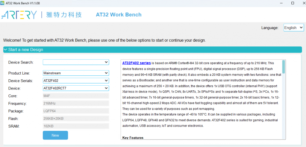
- Download Artery Workbench from the Artery Website https://www.arterytek.com/file/download/1710
- Open and create a new project using your selected IC. The example is made using an AT32F415RCT7. (First screenshot is wrong)
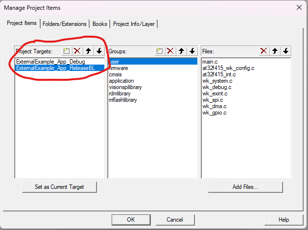
- We will create 2 same Projects. One for the Bootloader and one for the Application. Name them respectively.
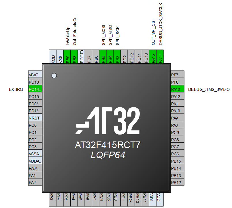
3. Next connect the interface to the Vision Controller as in your schematics. The following pins should be connected:
- „IRQ“ as GPIO ExtInt using Interupt with both edges
- „Fixture_Is_On“ as GPIO Output
- „Main_Wake_Up“ as GPIO Input
- „SPI_CS“ as GPIO Output
- „SPI_MISO“ as SPI MISO
- „SPI_MOSI“ as SPI MOSI
This can look like this:
Next we configure the different peripherals:
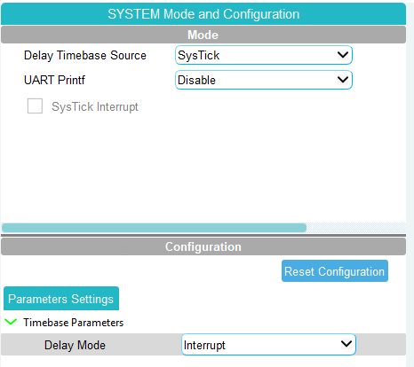
For the Library there is a time base necessary. Therefore we have to enable the SysTick in Interrupt mode.
The IRQ is set as EXINT Mode and should be configured like this:
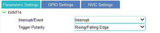
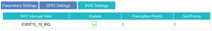
Make sure to enable the Interrupt. As stated in the Vision SPI library it is really important that this IRQ has a really high priority. So we let it on Priority 0!
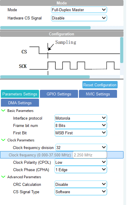
Next we have to configure the SPI. Configure it as follows:
- Full Duplex Master
- Clock Frequency should be not to high. Also it is not needed. As stated in the library documentation we choose a moderate clock frequency.
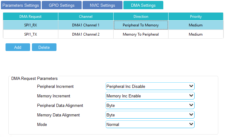
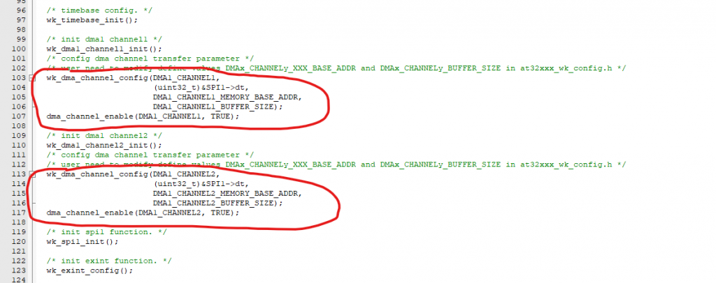
If your IC has the possibility to use the DMA then we use them in order to save CPU resources:
Also do not forget to enable the necessary interupts:
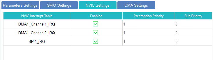
As discussed it is important that the IRQ EXTI has a higher interupt priority. Which is why we set the SPI IRQ and DMA Channel IRQ to 1.
That is all needed for now. Let’s generate the project for the used IDE. Just press Generate Code and put in your details:
Also due to the library is consuming a lot dynamic memory please set the Minimum heap size at least to 0x400
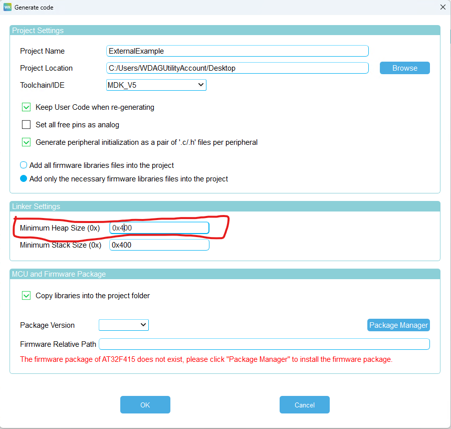
We generate a Project for the Application and one Project for the Bootloader.
Before integrating the necessary libraries we have to set up the Interupts for the needed peripherals. These function are needed in both the Application and Bootloader Project.
Both will be using the same modifications we do now.
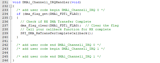
For the DMA SPI RX in wk_dma.c we will enable the interupt.

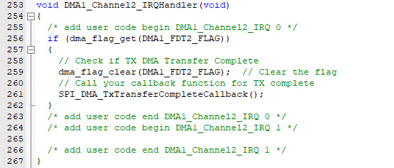
For the DMA TX in wk_dma.c we will enable the interupt.

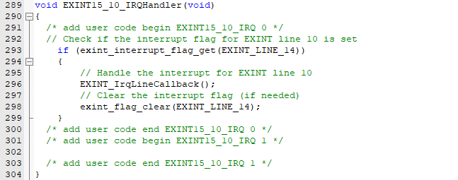
For the external EXINT Pin Interupt in wk_exint.c

For the SPI in wk_spi.c:

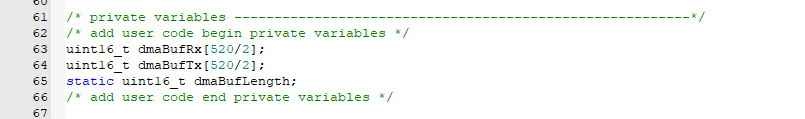
Starting with the main.c where we will implement all the hardware functions. Add the Buffer for the SPI Transfer using DMA. The buffer should be 520 Bytes. We align it 16 bit depending on the implementation and to be on the safe side.
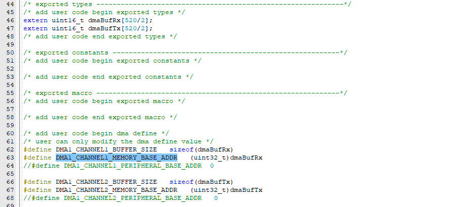
Next we will add the necessary configuration in the xxwk_config.h file:
Next we will implement the necessary interrupt handler functions:
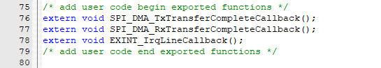
And export the necessary functions in the xx_int.h file:
We remove this lines because they make no sense in our use case:
Now we are ready to integrate the library. Download the Example from this page:
https://server.kk-t.eu/ExternalVision/ExampleSoftware
After downloading the example zip folder we have to extract the files. Best use WinRar to extract it.
It would be helpful to read the Documentation for the Vision SPI Library and the Vision RDM Library:
https://server.kk-t.eu/ExternalVision/SPIInterfaceVision
https://server.kk-t.eu/ExternalVision/RDMLibrary
Do not be confused with the naming scheme iQMesh. It is used in the libraries and means the same as Vision.
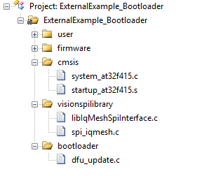
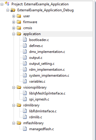
Then we copy the Bootloader and Application folder into our Project structure. Also we copy the Vision SPI Library (SPI_V3) and the Vision RDM Library (RDM) and the managedFlash library into our project.
Bootloader Project
First we will start making the bootloader project, therefore we open the Bootloader Project we have generated for the KEIL IDE:
Then we will add the source files for the spi library and the dfu. Only these are needed for the Bootloader project. Like this:
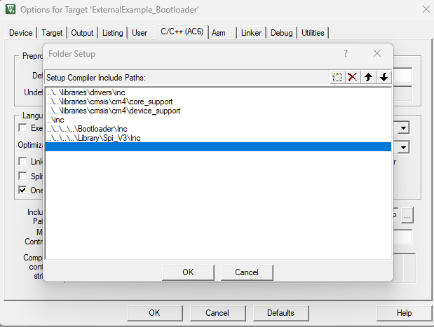
Make sure to include the necessary header files
Next we will modify the dfu_update.h header file to adjust it to our custom project.
Please modify this two defines according to the rdm definition of your product. If you have no rdm definition please get in touch with us.
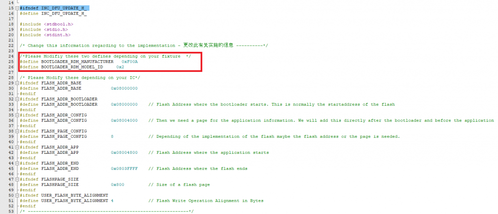
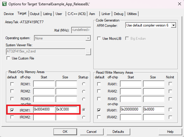
Please modify the flash defines according to your flash layout. For this project it looks like this:
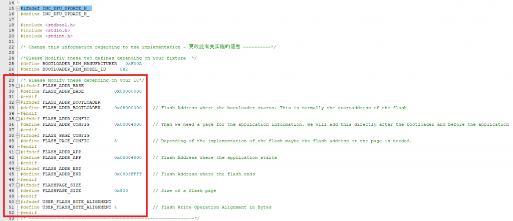
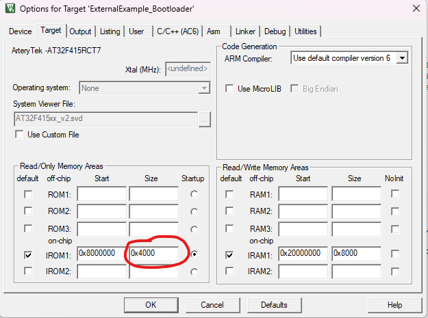
In order to make sure that the boot-loader does not get too big for the reserved flash size we will limit the flash size the boot-loader can use:
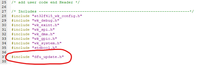
Next we have to call the necessary functions from the dfu update file in the main.c
Therefore we include the header file in the main.c:
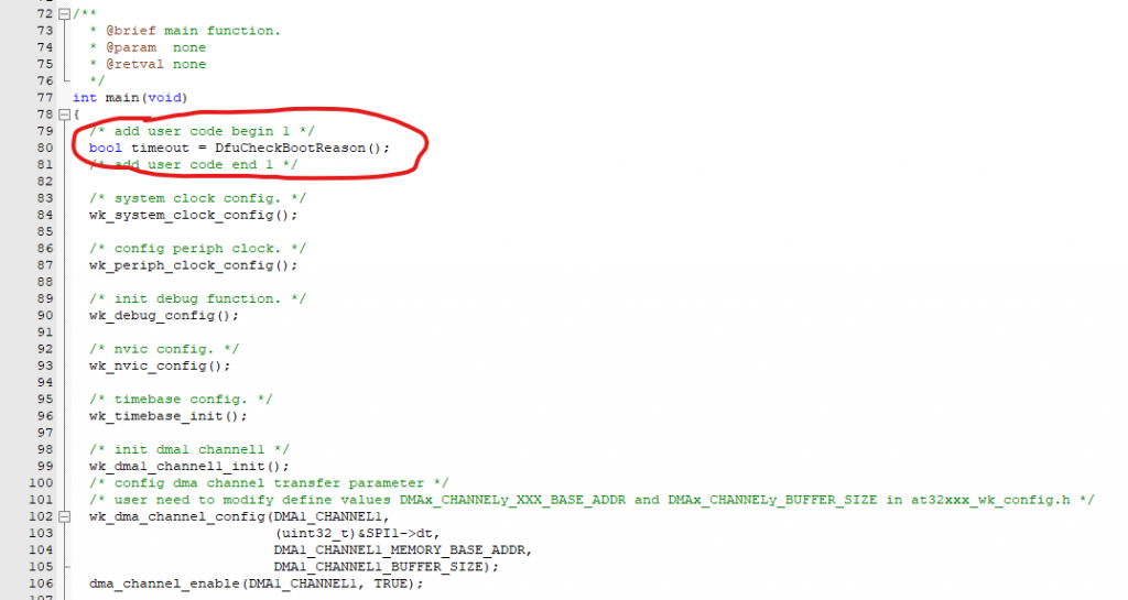
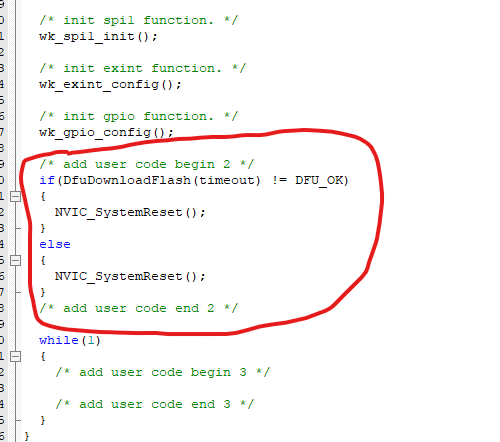
Add the „DfuCheckBootReason“ before any initialization is done:
Call the function „DfuDownloadFlash“ after the initialization is done:
At last step we have to link the extern hardware functions of the dfu_update.h file by implementing them.
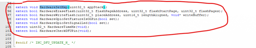
Therefore we have to define the necessary functions. Best in the main.c. These functions are hardware dependent.
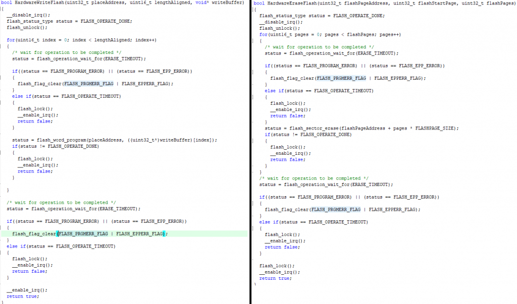
First we start with adding the „HardwareEraseFlash“ and „HardwareWriteFlash“ functions. They could look like this:
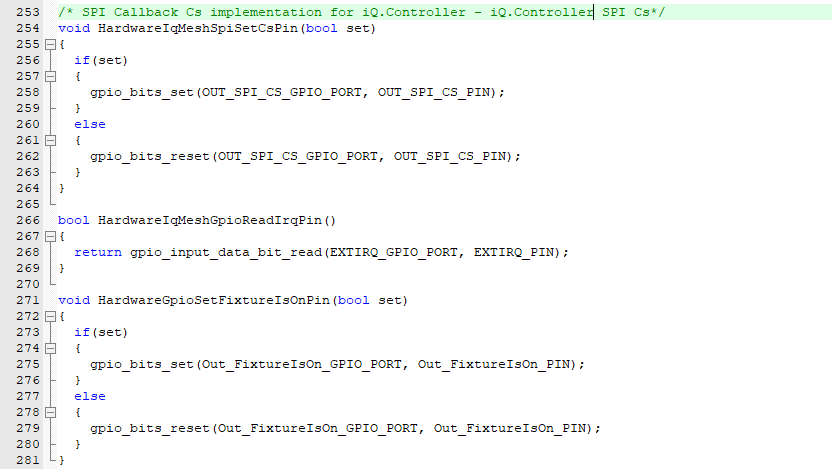
After that we will implement the other Hardware functions for the SPI CS Pin, IRQ Pin and FixtureIsOn Pin.
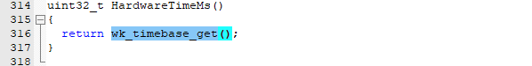
For the HardwareTimeMs we use the wk_timebase_get function:
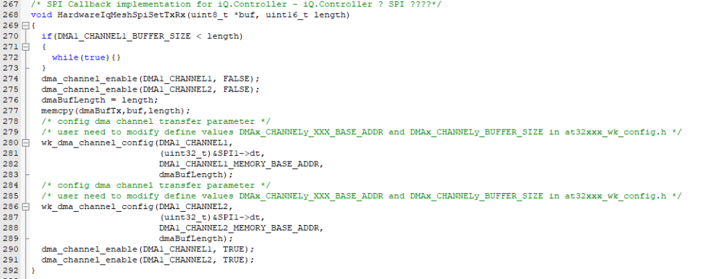
Next we will implement the Spi transfer function HardwareIqMeshSpiSetTxRx:
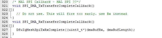
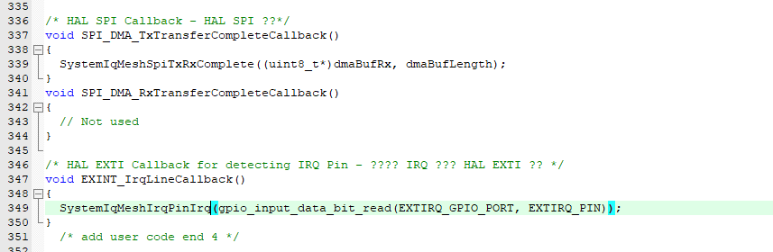
We have already prepared the necessary callback from the SPI DMA complete. This function we will implement next:
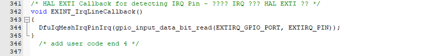
The EXINT Callback from the IRQ Pin:
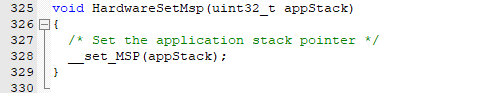
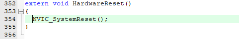
The last step is to add the HardwareSet MSP Function and some optional functions:
I would really recommend to implement this feature. This enables at startup of the fixture to stay in bootloader and receive data when for example a button is pressed. It can help prevent a failure if the firmware is bad!!

Application Project
In order to understand the code structure example it would be useful to take a look into the page of the example and read it:
The of the example application is as following: https://server.kk-t.eu/ExternalVision/ExampleSoftware
For the Application example it is nearly the same approach. We add again the necessary files for the application project:
Also include the necessary header files:
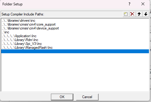
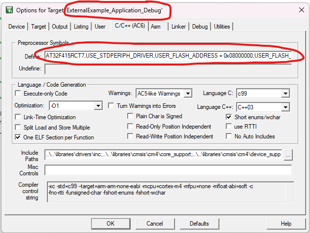
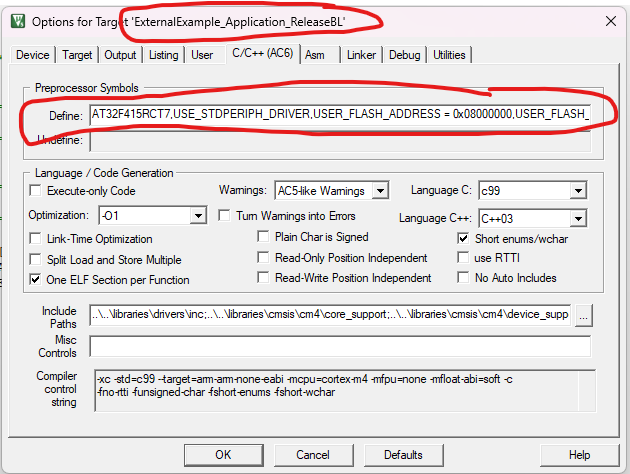
Next we need to define the necessary preprocessor information for the libraries. This defines are hardware dependent.
We will make the project as a debug version without a bootloader and as a release version which works together with a bootloader. Therefore we create Target „Debug“ and a Target „ReleaseBL“.
Then we have to define the flash start address for the application designed for the boot-loader:
Now we need the following preprocessor defines that the libraries can work.
| USER_FLASH_ADDRESS | Start of the Flash |
| USER_FLASH_START | Start of the Flash where the settings will be saved. Address after the application |
| USER_FLASH_SIZE | Start of the Flash where the settings will be saved. |
| USER_FLASH_PAGE_SIZE | Size of the flash pages. |
| USER_STORAGEOBJECTS | Count of the storage objects the user can save using the managed flash library. |
| USER_FLASH_BYTEALIGNMENT | Flash Write Operation Alignment in Bytes |
| USER_FLASH_ADDRESS_CONFIG (Release Only) | Flash Address where the Application information from the bootloader will be saved |
| USER_FLASH_ADDRESS_APP (Release Only) | Flash Address where the Application starts |
For the used example this values are used.
#DEBUG
DEBUG
USER_FLASH_ADDRESS = 0x08000000
USER_FLASH_START = 0x08003B000
USER_FLASH_SIZE = 0x5000
USER_FLASH_PAGE_SIZE = 0x800
USER_STORAGEOBJECTS = 7
USER_FLASH_BYTEALIGNMENT = 4

#RELEASE_BOOTLOADER
RELEASEBL
USER_FLASH_ADDRESS = 0x08000000
USER_FLASH_START = 0x0800E400
USER_FLASH_SIZE = 0x5000
USER_FLASH_PAGE_SIZE = 0x800
USER_STORAGEOBJECTS = 7
USER_FLASH_BYTEALIGNMENT = 4
USER_FLASH_ADDRESS_CONFIG = 0x08004000
USER_FLASH_PAGE_CONFIG = 8
USER_FLASH_ADDRESS_APP = 0x08004800
Keil does not have a good preprocessor handling so you have to copy this values into the following textbox using comma seperation:
Next we add the necessary includes into the main.c

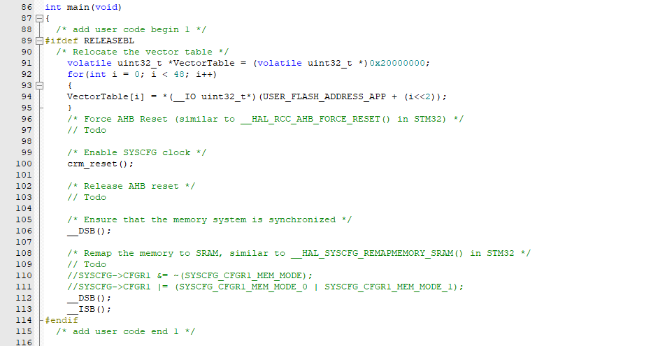
At startup when bootloader is in use make sure to reallocate the vector table and reset necessary configurations:
Attention: Some investigation is needed here for the artery controller ! Open Todo
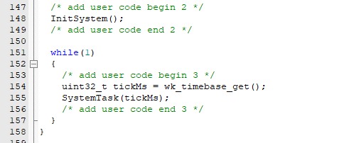
After initialization of the peripherals initialize the system. This is used as an example system. And call the SystemTask using the Timestamp in milliseconds.
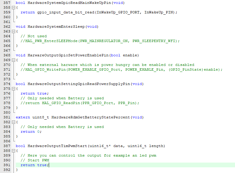
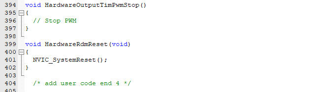
Next we add nearly the same Hardware functions as for the Boot-loader. Same behavior but we will have to link some functions using the system_implementation.h.
Functions which stay the same:
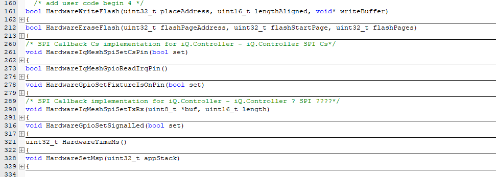
The callbacks we have to modify and call the functions from the system_implementation instead of the DFU:
Also we need to add some more. For the bootloader implementation:
For the system Implementation we need also the following implementations:
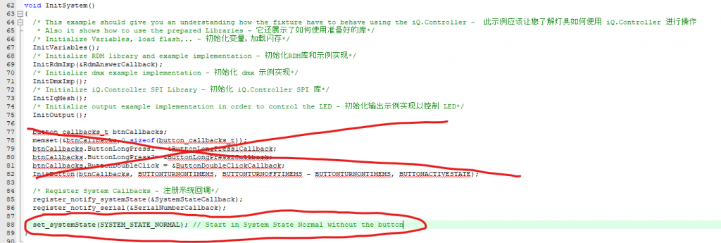
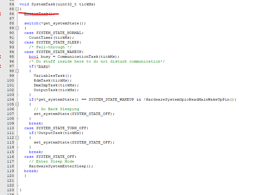
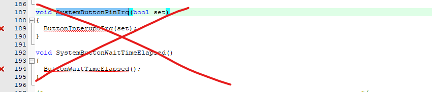
Now we have to modify the example system depending on our needs. The example contains also a button interface to turn on and more. That is not needed. We will remove the unnecessary code. Starting in the system_implementation.h and system_implementation.c file:
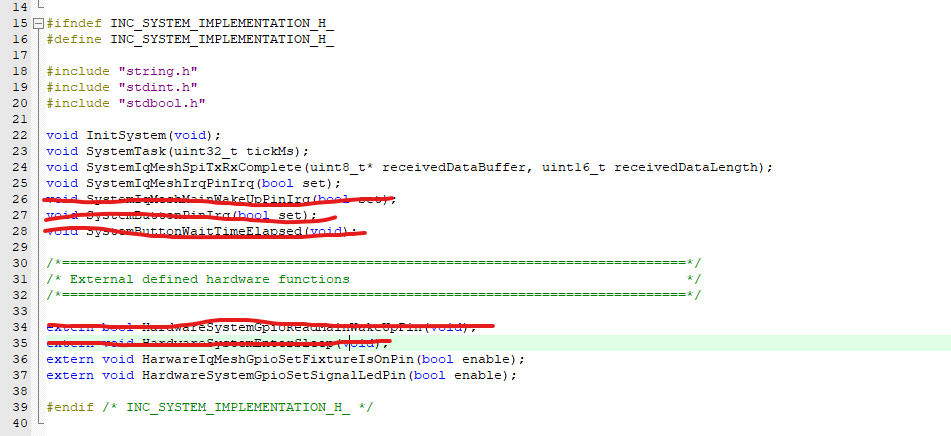
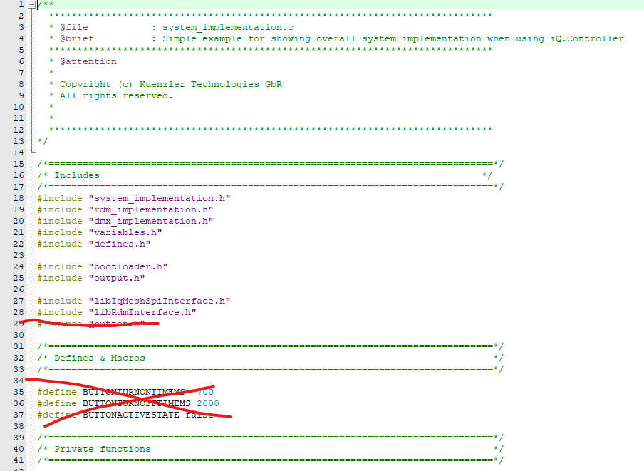
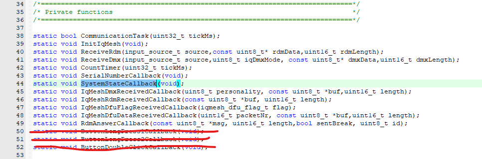
Remove the button and start immediately in system state normal:
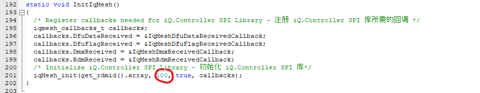
Modify the value of the iqMesh init function depending on your needs. It is the value of the dmx footprint you use for APP Control. Mostly the APP wants to have full control over all leds and in 16 bit. So it is mostly the longest dmx footprint. The value you put in can be longer but should not be less.
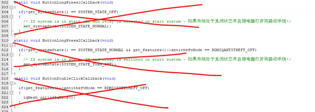
Remove other button functions:
So now the project should build successfully without error. Otherwise you have to check. Also please contact us for support. We are happy to assist you.
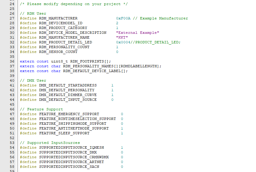
Next would be to change the defines depending on your needs. You can find them in the defines.c and defines.h files:
Next you should modify the dmx_implementation.c to match your dmx implementation for the product.
In the rdm_Implementation.c you have to adapt the rdm commands to your needs. After that you could try the example out.
Therefore please follow the steps on this page:
https://server.kk-t.eu/ExternalVision/TestPreparations
The full Project of the Example can be downloaded here:
https://kk-t.com/wp-content/uploads/2025/12/VisionExternalExample_CustomProject_2025_12_31.zip
If you have issues getting the communication between your IC and the Vision IC to work please follow the step by step debug instructions:
https://kk-t.com/wp-content/uploads/2025/08/iqMeshIntegration_DebugGuide.pdf
Analyse logs of Vision Wireless Controller
Flash the special firmware from below of your Vision Wireless controller to enable and view logs of the Vision Wireless Controller. The logs can be very helpful during the implementation process.
- Fanstel BT840 (nrf52840) :
On request - Wuerth Orphelia III /Proteus III (nrf52840) :
On request - Fanstel BC833 (nrf52833) :
https://server.kk-t.eu/api/v1/share/File?file=DEBUG_VISIONCONTROLLER_VISION_SPI_FBC833_APP5_6_3_SD_7_3_0_DEBUG_SPI_INTERFACE.bin - Abluetech PTR9818 (nrf52840) :
On request - Abluetech PTR9813/PTR9813+ (nrf52833) :
https://server.kk-t.eu/api/v1/share/File?file=DEBUG_VISIONCONTROLLER_VISION_SPI_FBC833_APP5_6_3_SD_7_3_0_DEBUG_SPI_INTERFACE.bin
WARNING: Dev only. Never flash on serial/production units.
- Open SEGGER J-Flash
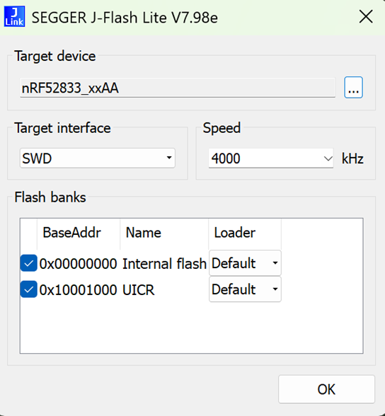
2. Select your controller. This documentation is with the nRF52833
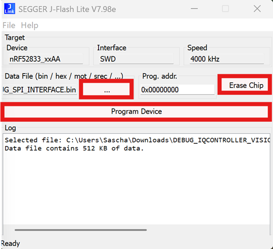
3. Load the special firmware file from above
4. Click Erase Chip
5. Click Program Device
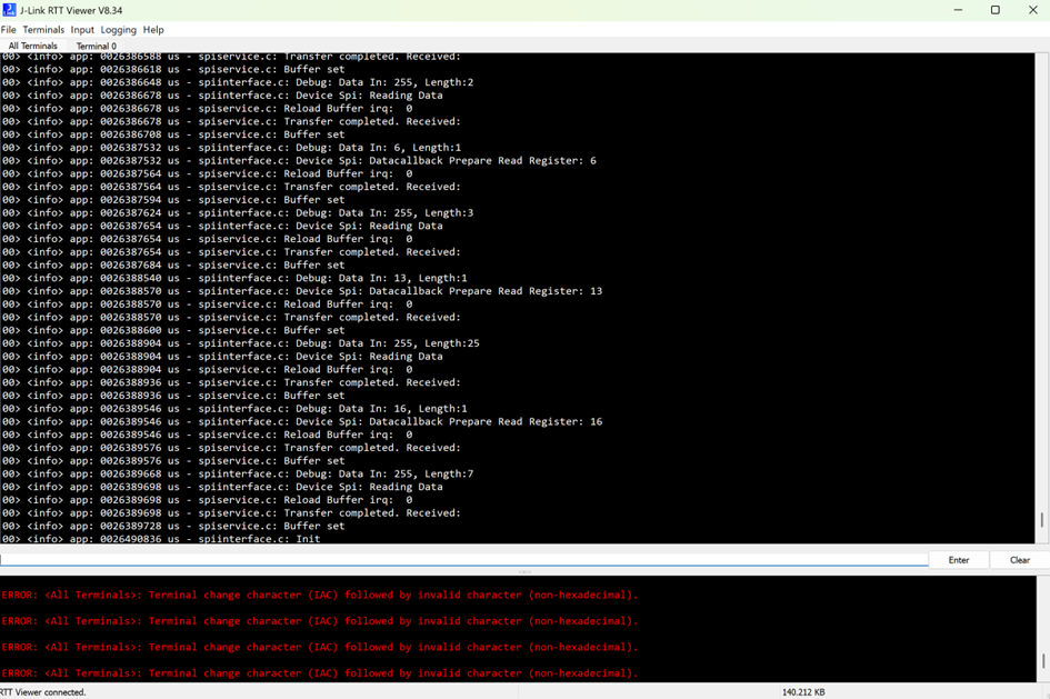
6. Open J-Link RTT Viewer
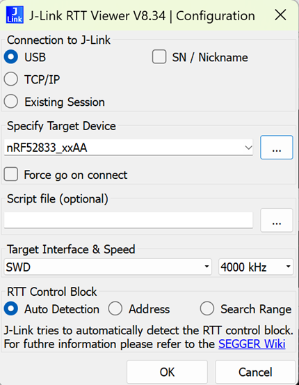
7. Review the logs of the Vision Wireless Controller: