In this section we will explain step by step how to get your own implementation for your specific product.
First to start with your custom implementation is that you have to choose your Vision Module.(depending on the size, availability and pricing)
We already have a list on working modules you can take a look and choose from:
https://server.kk-t.eu/ExternalVision/HardwareOverview
Just Browse on the left under Hardware Modules. There you can find detailed schematics and explanations.
For this explanation here we choose the Würth Ophelia III Module. The same used for the Vision External Example PCB. (https://server.kk-t.eu/ExternalVision/Hardware2 Here is the necessary information for it)
Then create your schematics using the information you find there. Now you have to connect the necessary pins with the Pins of your Main IC. Following pins must be connected with your main IC:
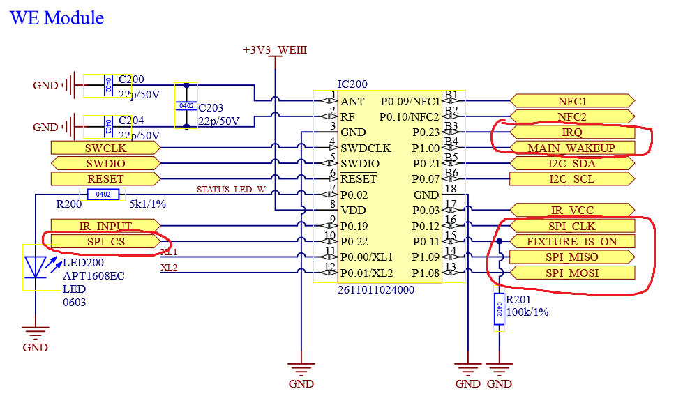
The Pins are:
- IRQ (GPIO)
- MAIN WakeUp (GPIO/EXINT)
- FIXTURE_IS_ON (GPIO)
- SPI CS (GPIO)
- SPI MOSI (SPI Function)
- SPI MISO (SPI Function)
- SPI CLK (SPI Function)
As you can recognize the communication via your main ic and the vision ic is done via SPI. But no worries as long as your main Ic supports SPI we have got you covered. We have plenty of examples and libraries which do everything for you.
So now lets connect the Pins to our main IC with respect of the functional layout of the used IC. As in the Vision Example we are using the an STM32F051:
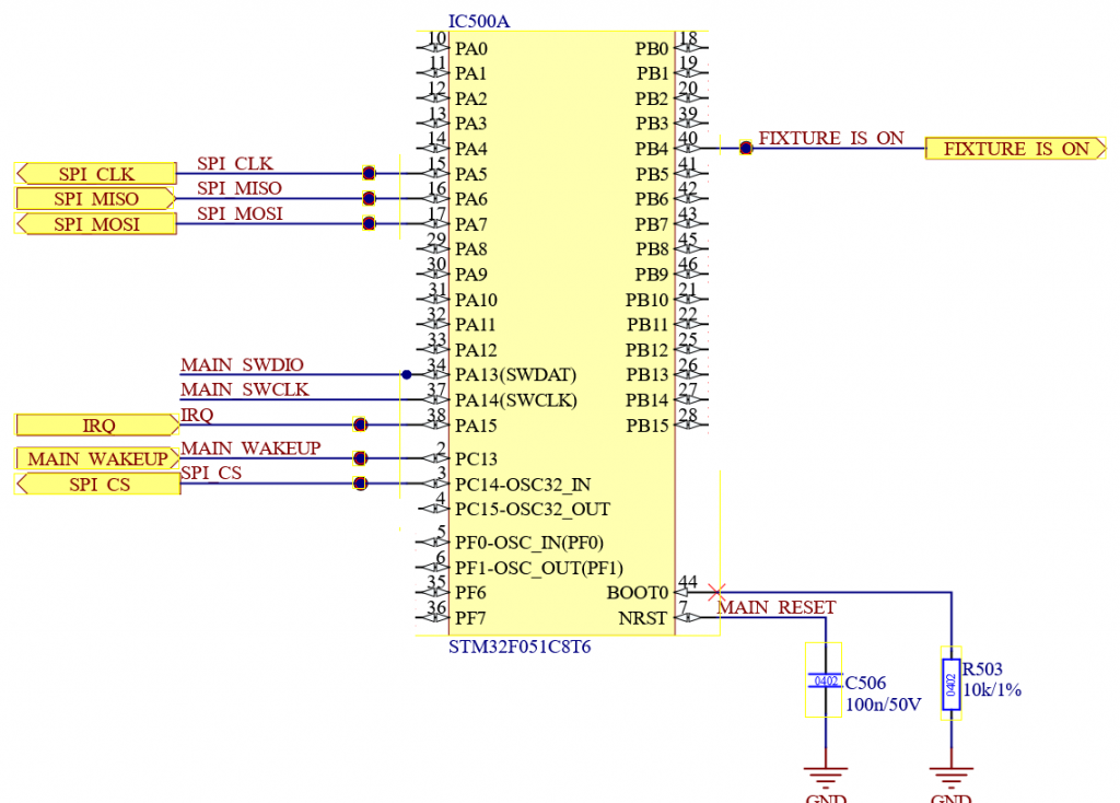
Now everything we need for the Vision External Module (IC) is connected. Feel free to add your own functions for your product now.
After creating the PCB you can start developing the firmware. Therefore please take a look at the following instructions:
- STM32 Main IC:https://server.kk-t.eu/ExternalVision/ExampleCustomStm32
- Artery Main IC: https://server.kk-t.eu/ExternalVision/ExampleCustomArtery