The Vision External Example should show you the functionality of the whole system using a simple PCB. You can use it to test your own implementation or to get started with the example code provided. On this board all additional components are available:
- Motion Sensor
- NFC Antenna
- IR Receiver
- Battery Charger, Battery Gauge, Battery (May not soldered on your PCB)
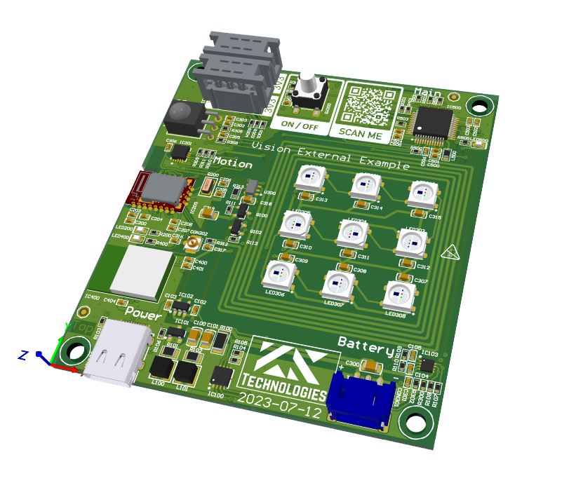
The PCB should be supplied using power from USB. Therefore just plug in the USB-C connector with a common USB power source. The module comes preflashed with a bootloader and firmware for the Vision Controller and the Maincontroller.
- Plug in USB-C and connect it to a charger
- Press Turn on button
- Led should light up white and show an red or green animation
Now you are ready to test the specific functions of the app. If you want to test your own application go ahead with the chapter „Test & Run“.
If there is something wrong with the PCB, then may flash the firmware again. For the Vision controller you can find the files under the chapter „Test & Run“ too. For the Main controller you can find the bootloader of the example firmware under „Example Project -> Software“.